Power electronics / System integration
Multi-inverter controller
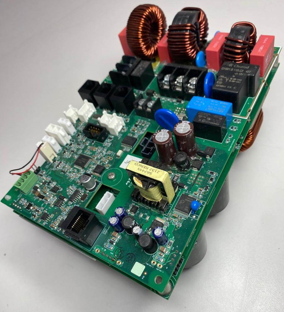
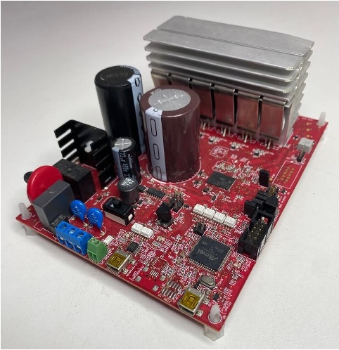
A published 2 kW controller combining active PFC, two three-phase inverters, sensing, and CAN communication.

DTFC motor control. Simulation with the real firmware. A reusable software foundation that connects performance, platform flexibility, and cost.
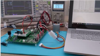
Original engineering photograph from Theta’s supplied presentation.
American company./Brazilian engineering./Global capability.
PLANO, USA ↔ JOINVILLE, BRAZILSix connected engineering choices that shape performance, development effort, and product cost. Outcomes depend on the application and its validation.
Connect torque and flux control with the motor, inverter, and application.
Discover DTFC02 / SIMULATIONExplore firmware, motor, and inverter behavior before final hardware is available.
Explore TSF03 / REUSEKeep the motor-control library. Add the modules that make each product different.
See the shared core04 / FLEXIBILITYSeparate MCU-specific interfaces from reusable libraries to support vendor and platform choice.
Explore portability05 / DEVELOPMENTReuse software and develop hardware and firmware in parallel to support a faster engineering path.
See the development approach06 / COSTEvaluate Cortex-M0+, single-shunt sensing, board integration, and software reuse together.
Explore cost optionsExplore the engineering behind the promise: a reusable firmware architecture, original signal plots, and work at the development bench.
Bring the motor, inverter, and firmware into one development discussion. Examine alternatives and operating conditions while the hardware is still taking shape.
See how TSF supports development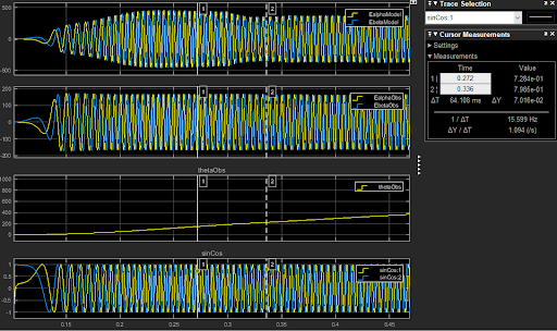
Reuse the control library across products and MCU platforms. Evaluate M0+ and single-shunt implementations to connect engineering efficiency with hardware cost.
A modular foundation helps reduce repeated engineering while each product retains its own integration and verification requirements.
Bring Theta into the engineering decisions that shape a new product, strengthen an existing platform, or connect a product to its operation.
Connect requirements, simulation, motor control, custom electronics, and firmware from concept through prototype evaluation and production support.
Evaluate cost, field feedback, motor upgrades, retrofit, and product variants. Shape a practical engineering roadmap beyond Start of Production.
Bring embedded communication, telemetry, cloud integration, and maintenance use cases into the product’s wider operating context.
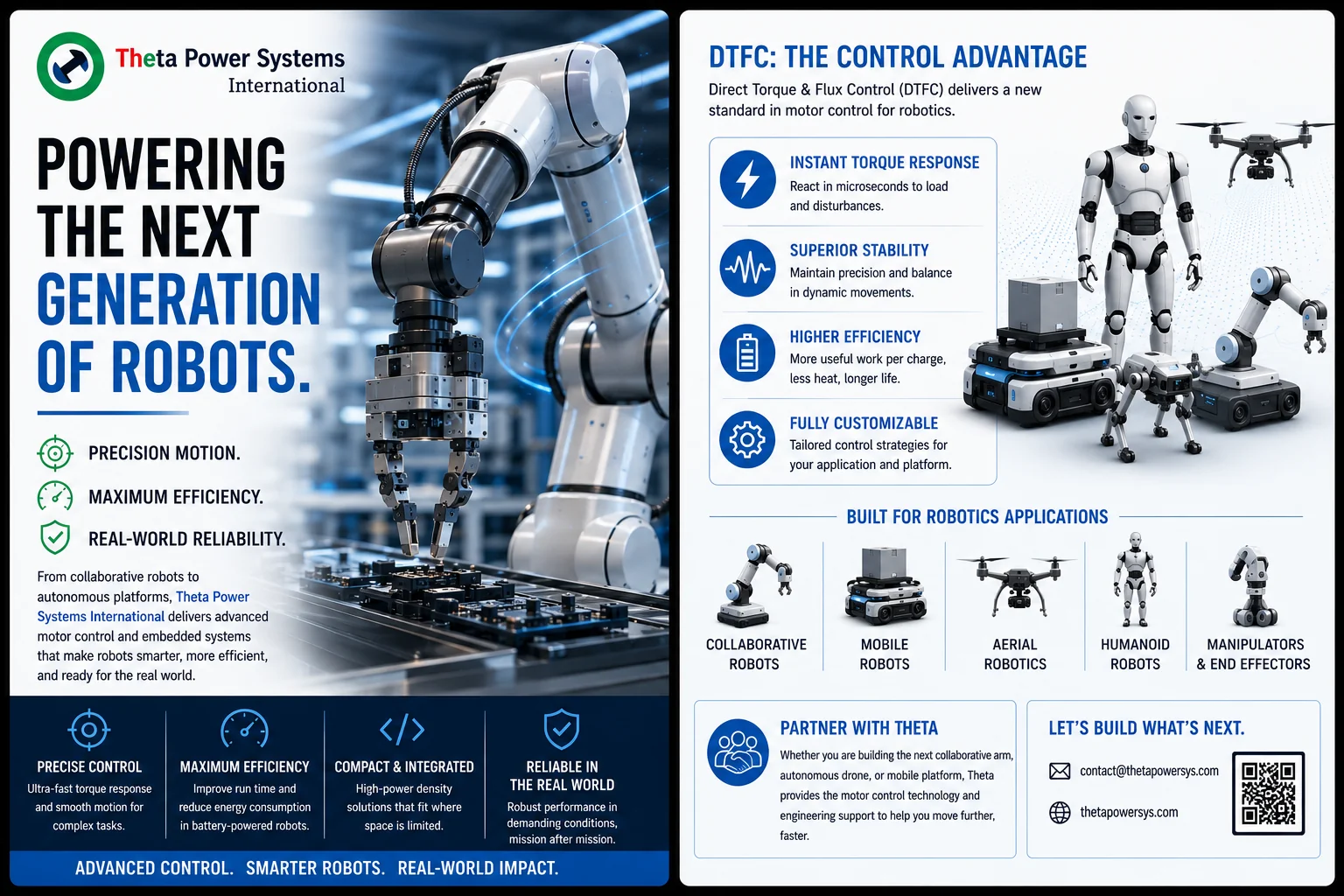
Actuators, motion, and the engineering behind control.
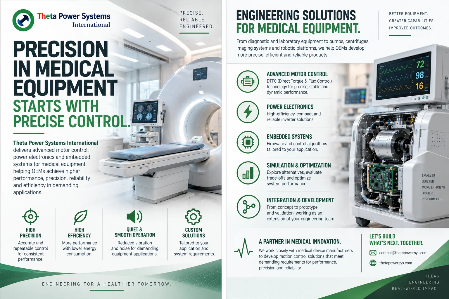
Motor control and electronics aligned with OEM equipment requirements.
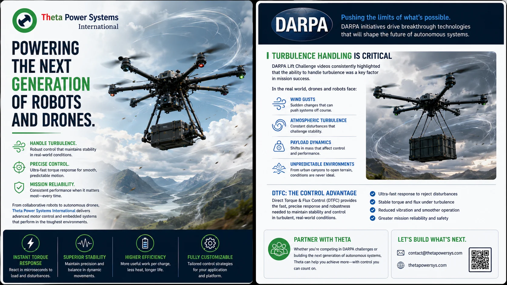
Motor, inverter, and control engineering for propulsion development.
Theta hardwareIntegrated electronics for appliance and thermal-management systems.
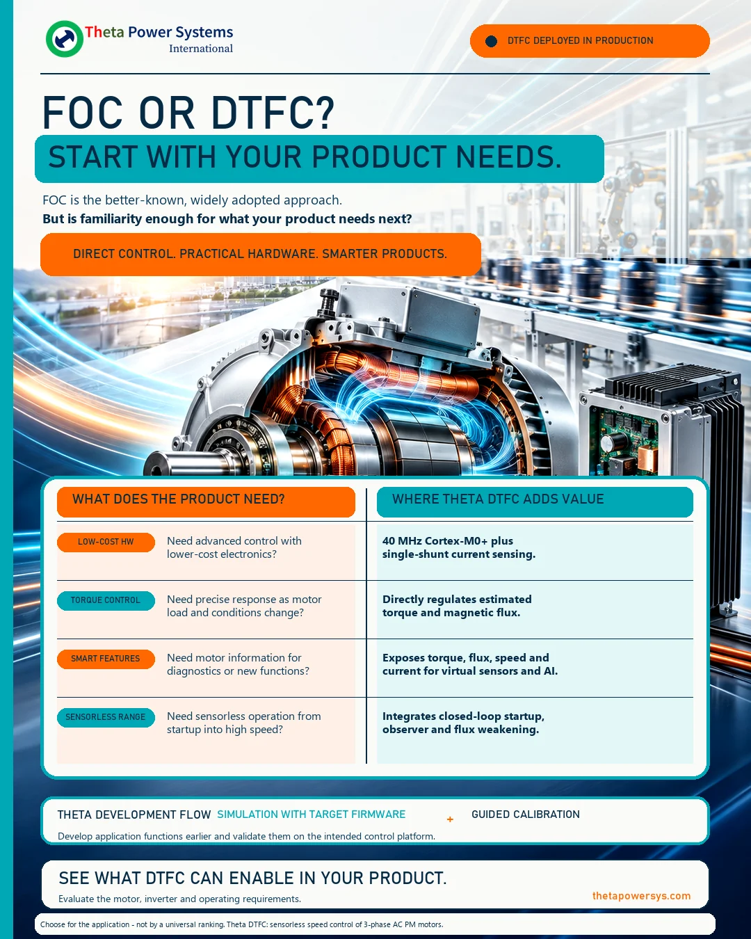
Control developed around the motor and its physical load.
 Theta hardware
Application-specific embedded and power electronics.
A published 2 kW controller combining active PFC, two three-phase inverters, sensing, and CAN communication.
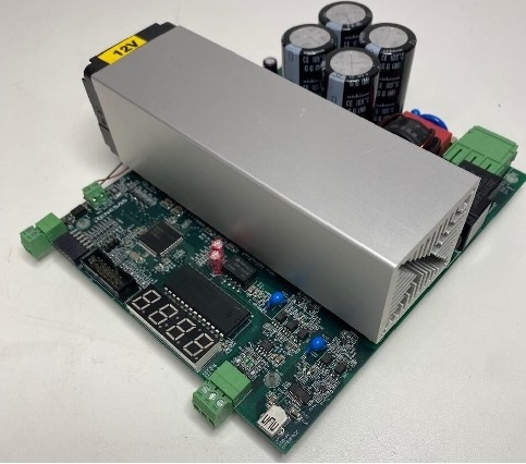
A published 2 kW three-phase inverter design with USB and RS485 / Modbus communication.
A published 600 W inverter evaluation board featuring an isolated onboard J-Link and isolated UART.
Bring your requirements. Let’s explore the engineering together.