01 / STANDSTILL
Stator resistance Rs
Use two DC current levels during rotor alignment. The voltage–current slope estimates Rs; the intercept estimates the inverter dead-time drop for later use.

New methods, development tools, and technical perspectives across motor control and product engineering.
Automatic identification of Rs, Ld, Lq, and magnet flux linkage supports sensorless PMSM control using the inverter’s existing hardware.
In a sensorless DTFC, motor parameters affect the observer’s angle estimate. The supplied study explores how identification and correct timing compensation help the model match the motor.
These results describe the supplied simulation study. Performance on physical motors and inverters must be established for the target application.
Explore the DTFC architecture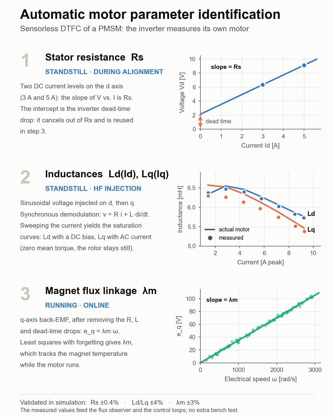
Use two DC current levels during rotor alignment. The voltage–current slope estimates Rs; the intercept estimates the inverter dead-time drop for later use.
Inject a high-frequency sinusoidal voltage on d and q axes, with synchronous demodulation. Current sweeps identify saturation curves; the q-axis method uses zero-mean-torque AC excitation.
Estimate flux linkage from q-axis back-EMF after accounting for resistance, inductance, and dead-time drops. The online estimate follows magnet-related changes during operation.
The carousel reports the following identification errors in its simulated setup with the real firmware.
The supplied simulation shows stable-speed limits of 2,815 rpm with compensation in the wrong direction and 3,271 rpm without compensation. With compensation in the correct direction, the test remained stable to 6,000 rpm, where it was stopped. These values describe this test setup, rather than a universal speed rating for DTFC.
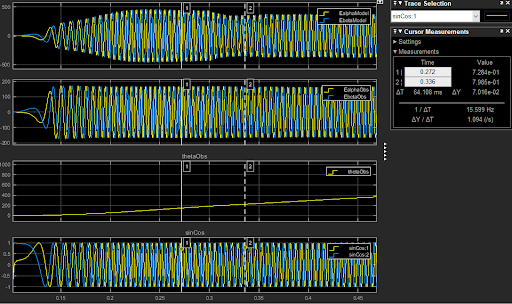
Theta’s proprietary framework simulates its own firmware code with interchangeable inverter models, power inputs, and motor parameters or types.
Develop hardware, firmware, and motor control in parallel. Inspect currents, voltages, torque, efficiency, critical conditions, and protections before final hardware is available. Use the same approach for troubleshooting field issues and evaluating new algorithms.
The published article reports launches up to 3× faster than traditional development. This is Theta’s stated upper-end outcome; the project scope and comparison baseline determine the actual development schedule.
Bring your requirements. Let’s explore the engineering together.